



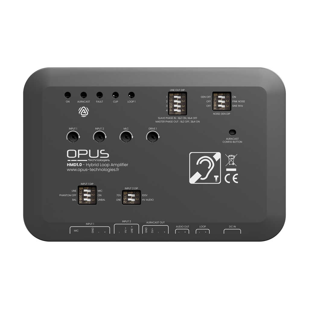
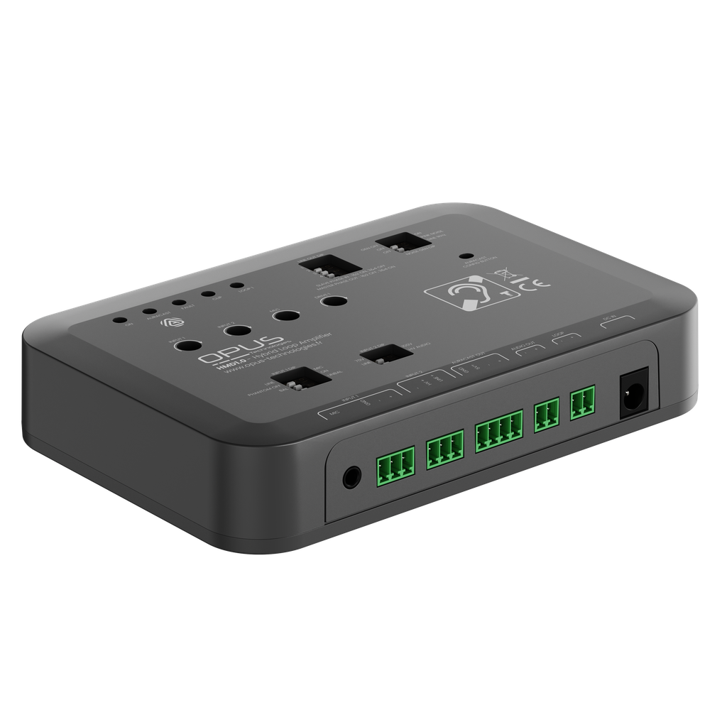
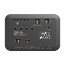
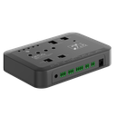
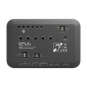

Opus Technologies HMD1.0 is a single-channel induction loop amplifier for medium-sized rooms such as meeting rooms, classrooms and TV rooms. It delivers sound to hearing aids set to the T position.
With the standard power supply (24 V / 3 A), the amplifier covers up to 100 m², and up to 150 m² with the optional PS-HMD32V power supply. Auracast™ broadcasting can be added later by connecting an Opus Auracast™ transmitter to the amplifier.
Features
- Loop output current 3.5 Arms, 4.2 Arms with the PS-HMD32V power supply
- Two inputs: a line input and an input for line, 70 V, 100 V or high-level audio
- 12 V microphone phantom power, enabled with a DIP switch
- Automatic gain control (AGC) with voice-optimised peak detection
- Adjustable metal loss compensation (MLC)
- Built-in signal generator: pink noise and 1 kHz
- Configuration with DIP switches, input and output level adjustment with potentiometers
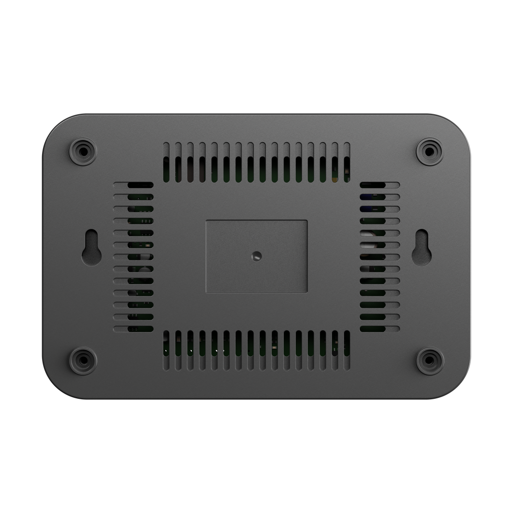
- Mounting on a wall or in an equipment cabinet
Package contents
HMD1.0 – amplifier
- HMD1.0 amplifier
- External power supply 24 V / 3 A
HMD1.0-SA – room kit
- HMD1.0 amplifier
- External power supply 24 V / 3 A
- OP-IL50 loop cable, 30 m
- OP-M surface microphone
- RCA cable
- Phoenix connectors
- Screwdriver
- IEC sticker indicating that the area is equipped for people with hearing loss
HMD1.0-TV – TV kit
- All components of the HMD1.0-SA kit
- OP-TosLink converter for the television’s digital audio
Technical specifications
- Power supply: 24 V DC, 3 A, external power supply (PS-HMD32V optional)
- Input 1: line input, balanced or unbalanced
- Input 2: line, 70 V, 100 V or high-level audio
- Loop output: 1, 2-pin connector, 3.5 mm pitch
- Output voltage: max. 48 Vpp depending on loop characteristics
- Frequency response: 100 Hz – 6 kHz (−3 dB) depending on loop characteristics
- Auracast™: not integrated; transmitter connection on the PCB or a 4-pin terminal block
- Dimensions: approx. 100 × 150 × 24 mm
Installation
Mount the amplifier on a wall or in an equipment cabinet and connect the audio source to its dedicated input. Choose the loop cable cross-section and layout according to the recommendations of the Opus SmartLoop simulation software, and adjust the amplifier to the IEC standard using the OP-FSM field strength meter, sold separately.